
Guide to Silicon Nitride Ceramic Sleeve Dimensions and Tolerances
Silicon nitride (Si₃N₄) ceramic sleeves are precision tubular components used in demanding engineering applications where metallic alternatives fail due to wear, corrosion, or thermal stress. For design engineers and procurement specialists, understanding the dimensional capabilities and tolerance classes of these components is essential for successful integration into assemblies.
Unlike metals, which can be machined with relative ease after forming, ceramic sleeves require careful consideration of manufacturing constraints. The sintering process produces near-net shapes, and final dimensional accuracy is achieved through diamond grinding—an expensive but necessary secondary operation.

Definition: What Are Silicon Nitride Ceramic Sleeve Dimensions and Tolerances?
Silicon nitride ceramic sleeve dimensions refer to the critical geometric parameters including inner diameter (ID), outer diameter (OD), length, wall thickness, and additional features such as flanges, slots, or stepped bores. Tolerances are the permissible deviation limits from specified dimensions, typically expressed as ± values in millimeters.
For precision engineering applications, these tolerances directly affect assembly fit, running clearance, and functional performance. Typical commercial tolerances range from ±0.02 mm to ±0.05 mm for critical dimensions, with high-precision machining achieving ±0.005 mm in specialized cases.

Common Dimensional Ranges for Silicon Nitride Sleeves
Inner Diameter (ID) Specifications
The inner diameter is arguably the most critical dimension, as it determines the fit with the mating shaft or component. Based on industry practice, the standard manufacturing capability for inner diameters generally spans from 5 mm up to 120 mm. For specialized industrial equipment, larger bores can be accommodated, though these require extended processing times and careful quality control.
Key considerations when selecting an inner diameter include the nominal shaft size plus the required running clearance, expected thermal expansion at operating temperatures, the chosen assembly method (whether press-fit or slip-fit), and the surface finish requirements for sealing or bearing surfaces.
For shaft sleeve applications in pumps and mechanical seals, inner diameters are typically matched to standard shaft diameters with clearance allowances of 0.02 to 0.05 millimeters, depending on the operating temperature and rotational speed.
The outer diameter interfaces with the housing, bearing journal, or retention mechanism. Manufacturing capabilities generally allow for outer diameters designed to customer specification, usually matching standard bearing or housing bores. The wall thickness is a derived dimension calculated from the difference between outer and inner diameters.
Wall thickness considerations fall into several categories. Standard configurations offer a balance of strength and manufacturability. Thin-wall designs, typically under 3 millimeters, are employed for weight reduction or space constraints, though they require more careful handling during grinding. Thick-wall designs, exceeding 10 millimeters, are specified for increased mechanical strength or greater thermal mass in high-temperature applications.
Length Specifications
The practical length limit for a single-piece silicon nitride sleeve is approximately 300 millimeters. For applications requiring longer sleeves, manufacturers may produce extended lengths with specialized furnaces and fixturing, though practical limitations arise from sintering distortion and grinding capabilities. Length tolerances typically follow the same precision classes as diameters, though the achievable tolerance is less stringent for very long parts due to cumulative straightness errors.

Dimensional Tolerance Classes for Silicon Nitride Sleeves
Understanding achievable tolerances helps designers specify appropriate precision levels without over-specifying and increasing cost unnecessarily.
General Tolerances (Commercial Grade)
For standard industrial applications, commercial-grade tolerances are typically specified as follows. Inner and outer diameter tolerances generally fall within ±0.02 to ±0.05 millimeters. Length tolerances are somewhat broader, ranging from ±0.10 to ±0.30 millimeters. Form tolerances such as roundness are held to 0.01 to 0.02 millimeters, while cylindricity and concentricity are typically maintained within 0.01 to 0.05 millimeters. This tolerance class is suitable for most general-purpose sleeve applications in pumps, conveyors, and material handling equipment.
High-Precision Tolerances
For demanding applications such as high-speed spindles, precision bearings, or metering pumps, significantly tighter tolerances are achievable through advanced grinding and lapping processes. Precision-grade inner and outer diameter tolerances can be held to ±0.005 to ±0.01 millimeters. Length tolerances in this class improve to ±0.05 to ±0.10 millimeters. Roundness and cylindricity can be refined to 0.001 to 0.005 millimeters, with concentricity maintained within 0.01 to 0.02 millimeters. The precision of ceramic machining has been demonstrated down to 0.001 millimeters for specialized applications, though this typically involves multiple grinding passes, dedicated fixturing, and stringent environmental controls.
Factors Influencing Dimensional Tolerance Selection
Assembly Fit Requirements
The intended assembly fit—whether clearance fit, transition fit, or interference fit—directly determines tolerance requirements. For clearance or slip fits where the sleeve and shaft can move relative to each other, typical clearances range from 0.02 to 0.05 millimeters, commonly used in rotating applications and plain bearings. For interference or press fits where the sleeve is forced onto the shaft creating compressive stress, typical interference values range from 0.01 to 0.03 millimeters per 10 millimeters of shaft diameter, commonly used in pump sleeves and retention applications.
Thermal Expansion Considerations
Silicon nitride has a coefficient of thermal expansion (CTE) of approximately 3.2 × 10⁻⁶ per degree Celsius over the range of 20 to 1000 degrees Celsius. This is significantly lower than most metals, with steel exhibiting roughly 12 × 10⁻⁶ per degree Celsius. When designing sleeve-to-shaft clearances, two critical scenarios must be evaluated. For room temperature installation, the clearance must account for differential expansion at operating temperature. For high-temperature operation, the sleeve expands less than the metal shaft, potentially reducing clearance or creating unintended interference. Engineers must calculate the effective clearance at maximum operating temperature to prevent seizure.
Surface Finish Requirements
Surface finish directly impacts tolerance achievement and functional performance. For standard industrial applications, a surface finish of Ra 0.4 to 0.8 micrometers is typically sufficient. Mechanical seal applications demand smoother finishes in the range of Ra 0.2 to 0.4 micrometers on sealing surfaces. Precision bearing applications require Ra 0.05 to 0.2 micrometers to minimize friction and wear at high speeds. Ultra-precision applications, such as optical or specialized instrumentation components, may demand surface finishes below Ra 0.05 micrometers, achieved through lapping and polishing processes.
Additional Dimensional Features
Stepped Bores
Some sleeve designs incorporate stepped bores for locating features, retaining rings, or seal retention. These introduce additional dimensional requirements including step diameter and position tolerances, shoulder squareness relative to the bore axis, and radius or chamfer specifications at transitions.
Flanges and Shoulders
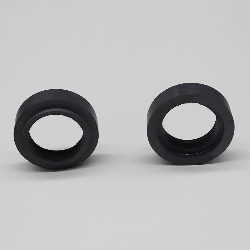
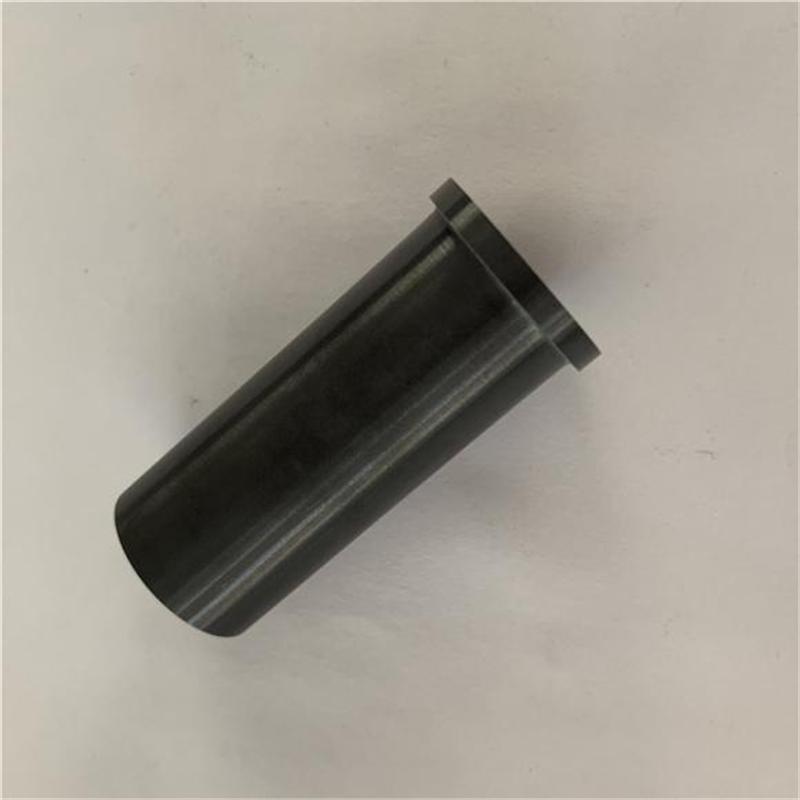
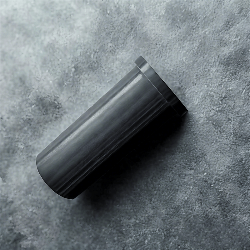
Flanged sleeves require additional consideration of flange outer diameter and thickness, flange face flatness and perpendicularity to the sleeve axis, and bolt hole patterns if the flange is designed for bolted retention.
Slots and Through-Holes
Side slots can provide elastic deformation for easier installation, while through-holes may serve as lubrication ports or locating features. Tolerances for these features depend on their functional purpose, with locating features typically held to tighter tolerances than simple clearance holes.
Material Considerations for Silicon Nitride Sleeves
Silicon nitride’s material properties directly influence achievable dimensions and tolerances. The material has a density of 3.20 to 3.30 grams per cubic centimeter, providing a favorable strength-to-weight ratio. Flexural strength ranges from 700 to 1000 megapascals, allowing for thin cross-sections under load. Hardness is in the range of HRA 90 to 94, comparable to 9 on the Mohs scale, which necessitates diamond tooling for machining. Fracture toughness of 6.0 to 10.0 megapascal-square root meters provides reasonable resistance to crack propagation. The maximum service temperature of 1200 degrees Celsius in oxidizing atmospheres makes it suitable for high-temperature applications. Thermal conductivity is moderate, approximately 15 to 23 watts per meter-kelvin, which affects thermal gradient management.
These properties explain why silicon nitride is chosen for demanding applications, but they also impose constraints on manufacturing and tolerance achievement. The hardness and low fracture toughness mean that any post-sintering machining must be performed with extreme care to avoid introducing surface flaws that could serve as crack initiation sites.
Practical Applications and Dimension Selection Guidance
Pump Shaft Sleeves
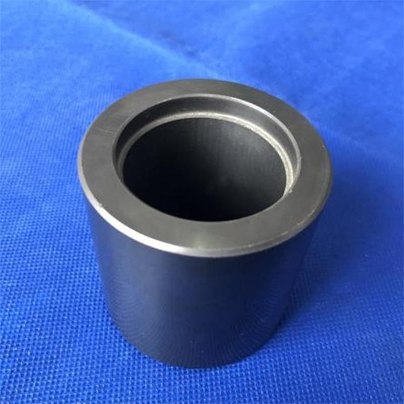
Pump applications typically require inner diameters matched to pump shaft diameters with 0.03 to 0.05 millimeters running clearance. The length is determined by stuffing box or seal chamber dimensions. Tolerances are typically specified at ±0.02 millimeters on inner diameter for seal surface accuracy. Surface finishes on sealing surfaces are maintained at Ra 0.2 to 0.4 micrometers.
Industry insight: For chemical pumps operating above 150 degrees Celsius, engineers should select the inner diameter clearance based on hot clearance requirements rather than cold fit. Because silicon nitride expands less than the metal shaft, the clearance decreases at operating temperature, and sufficient allowance must be provided to prevent contact under all operating conditions.
High-Speed Spindle Sleeves
CNC spindle applications demand tolerance of ±0.005 to ±0.01 millimeters for bearing surfaces. Roundness must be below 0.005 millimeters to minimize vibration and ensure smooth rotation. Surface finishes are specified at Ra 0.05 to 0.15 micrometers. Concentricity between inner and outer diameters is highly critical, as any eccentricity will cause imbalance at high rotational speeds.
Mechanical Seal Sleeves
Seal applications require precise inner diameter fit to the shaft with 0.01 to 0.02 millimeters clearance. End face perpendicularity must be within 0.005 millimeters to prevent seal leakage. Surface finish on the seal face is maintained below Ra 0.2 micrometers for compatibility with the mating seal ring material.
Manufacturing Methods and Tolerance Capabilities
Forming Processes
The primary forming method significantly affects achievable tolerances. Isostatic pressing provides uniform density distribution for complex shapes. Injection molding allows complex features such as undercuts and threads, but requires careful sintering control due to binder removal and differential shrinkage. Slip casting offers an economical option for simple tubular shapes.
Sintering
Silicon nitride sintering typically occurs at temperatures of 1700 to 1850 degrees Celsius. Sintering shrinkage is approximately 15 to 20 percent linear, which must be precisely controlled for dimensional accuracy. Differential shrinkage can occur in complex geometries, requiring careful tool design to compensate.
Post-Sintering Machining
Finished dimensions are achieved through diamond grinding. General grinding holds tolerances of ±0.02 to ±0.05 millimeters. Precision grinding achieves ±0.005 to ±0.01 millimeters. Lapping and honing are employed for ultra-precision work at 0.001 millimeter levels and for achieving superior surface finishes.
Machining considerations: Diamond grinding wheels are necessary due to material hardness. Internal grinding of small inner diameters under 10 millimeters presents challenges related to wheel contact and chip evacuation. Length-to-diameter ratios exceeding 5 to 1 require special attention to avoid deflection and taper errors during grinding.
Common Design Mistakes and Mitigation
Over-Specifying Tolerances
Specifying unnecessarily tight tolerances increases cost without functional benefit. Engineers should consider whether the intended fit truly requires the tolerance specified, whether assembly methods can accommodate less stringent tolerances, and whether the operating environment makes tight tolerances impractical. A careful functional analysis often reveals that only a few critical dimensions require precision tolerances.
Ignoring Thermal Effects
Failing to account for differential thermal expansion between the ceramic sleeve and metal shaft can lead to seizure at operating temperature from insufficient expansion allowance, excessive clearance if expansion was overestimated, or thermal stress cracking if interference becomes excessive at elevated temperatures.
Neglecting Installation Forces
Ceramics are brittle and sensitive to impact. Press-fit interference should be limited to avoid cracking. Sharp edges should be chamfered, typically 0.2 to 0.5 millimeters at 45 degrees. Installation tools should distribute force evenly rather than applying localized loads.
Frequently Asked Questions
1. What are the standard inner diameter tolerances for silicon nitride sleeves?
Commercial-grade silicon nitride sleeves typically achieve ±0.02 to ±0.05 millimeters on inner diameters. For high-precision applications requiring bearing-grade accuracy, tolerances can be tightened to ±0.005 to ±0.01 millimeters with additional grinding operations. Specific tolerances should be specified based on the functional requirements of the assembly, such as the desired fit class and operating conditions.
2. How tight can the dimensional tolerance be for a silicon nitride ceramic sleeve?
State-of-the-art silicon nitride machining can achieve tolerances as tight as ±0.001 millimeter (one micron) for specialized applications. This level of precision requires advanced grinding equipment, stringent quality control, and significantly higher manufacturing costs. Most industrial applications are served by ±0.005 to ±0.02 millimeter tolerances, which provide a practical balance between precision and cost.
3. What is the maximum length available for a silicon nitride sleeve?
Practical manufacturing limits typically restrict silicon nitride sleeve length to approximately 300 millimeters per piece. Longer sleeves are possible but require specialized equipment and careful processing to control straightness and tolerances. For extended lengths exceeding 300 millimeters, design engineers should consider dimensional limitations in the design phase or explore multi-piece assemblies.
4. How do thermal expansion considerations affect sleeve dimensions?
Silicon nitride has a thermal expansion coefficient of approximately 3.2 × 10⁻⁶ per degree Celsius from 20 to 1000 degrees Celsius. This is significantly lower than steel, which is approximately 12 × 10⁻⁶ per degree Celsius. When designing sleeve-to-shaft clearances for high-temperature operation, the differential expansion between the ceramic sleeve and metal shaft must be calculated to prevent seizure or excessive clearance at operating temperature.
5. What surface finish is achievable on silicon nitride sleeves?
Standard grinding achieves Ra 0.2 to 0.4 micrometers for general applications. Mechanical seal surfaces typically require Ra 0.05 to 0.1 micrometers. Ultra-precision lapping and polishing can achieve surface finishes below Ra 0.02 micrometers for specialized applications such as optical components or high-precision metrology standards.
6. Can silicon nitride sleeves be made with through-holes or slots?
Yes, silicon nitride sleeves can be machined with through-holes, slots, and other features using diamond grinding tools or ultrasonic machining. These features enable lubrication ports, locating holes, or elastic deformation slots for easier installation. Feature tolerances depend on size and complexity, with smaller features generally requiring more care to maintain dimensional accuracy.
7. What wall thickness should be specified for a silicon nitride sleeve?
Wall thickness depends on mechanical loading, thermal requirements, and installation method. Typical wall thicknesses range from 2 to 15 millimeters. Thin-wall designs under 3 millimeters require careful handling and may have more limited tolerance capabilities. Thick-wall designs exceeding 10 millimeters offer greater strength but increased weight and material cost. The optimal wall thickness balances structural requirements against manufacturing constraints.
8. How do I specify tolerances for a custom silicon nitride sleeve?
Engineers should work with the manufacturer to define critical dimensions and permissible deviations. Specify the intended fit (clearance, transition, or interference) and operating conditions including temperature and loading. Clearly identify sealing surfaces, bearing surfaces, and other functional features that require tighter tolerances. Allow reasonable tolerances for non-critical features to control cost. Providing a complete assembly drawing with functional requirements enables the manufacturer to propose cost-effective tolerance allocations.
Silicon nitride ceramic sleeves offer exceptional wear resistance, thermal stability, and corrosion resistance for demanding industrial applications. Understanding common dimensional ranges and achievable tolerances is essential for effective design and procurement.
Inner diameters typically range from 5 to 120 millimeters, with larger sizes available for specialized applications. Practical length limits are approximately 300 millimeters per piece. Commercial tolerances of ±0.02 to ±0.05 millimeters are suitable for most applications, while precision grades achieving ±0.005 to ±0.01 millimeters are available for demanding applications. Surface finishes range from Ra 0.2 to 0.4 micrometers for general purposes down to below Ra 0.1 micrometers for sealing and bearing surfaces.
When specifying dimensions and tolerances, consider the functional requirements of the assembly, installation methods, and the thermal environment. Over-specification increases cost without providing functional benefit, while under-specification may compromise performance or reliability. A balanced approach that assigns tight tolerances only to critical functional surfaces and allows broader tolerances for non-critical features provides the best value.
Why Use Silicon Nitride Sleeve Instead of Metallic Shaft Sleeve in Chemical Pumps
How Does Silicon Nitride Sleeve Compare with Alumina or Silicon Carbide Sleeves in Pump Applications